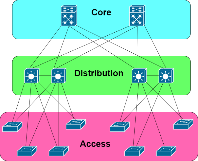
In this edition of the CCNA Series, we are going to cover network switches. In the CCNA exam topics, we are looking specifically at Network Fundamentals > Explain the role and function of network components > L2 and L3 switches. Before we get into the difference between Layer 2 and Layer 3 switches, let’s describe and understand what switches are and what their role is in a network. In their simplest form, switches are hardware or software devices that provide connectivity to the network. For the simplicity of this article, unless otherwise specified, we will be focusing on hardware based (physical) switches. Who and/or what do switches provide connectivity to the network? Well, that depends upon which “layer” the switch resides. In the traditional campus infrastructure model, we can look at the network as having three layers; access, distribution and core.
- Access Layer
- The switches at the access layer provide endpoints, or devices their initial connectivity to the network. The access layer can be thought of as the edge of the campus network, because this is where the network begins for devices. This is where our computers, printers, phones, and much more, connect to the network. The network is providing the service of delivering data to the required destinations for the connecting devices.
- Distribution Layer
- While the purpose of the access layer is for switches to connect to endpoints, the distribution layer switches connect to other switches. The distribution layer bridges the gaps between access layer switches at the local site (intra-site communication), and the local site access layer and the core layer, which provides connectivity to other sites (inter-site communication). The distribution layer provides two main functions, that both stem from the concept of network scalability.
- Acts as an aggregation layer for the access layer switches. As the number of access layer switches grows at a site, it is not functionally or cost effective to connect each access layer switch together directly to provide connectivity between them. It makes more sense to create a layer of switches “above” the access layer to provide the intra-site connectivity.
- Provides connectivity to the core layer which in turn provides connectivity to other sites (inter-site connectivity).
- While the purpose of the access layer is for switches to connect to endpoints, the distribution layer switches connect to other switches. The distribution layer bridges the gaps between access layer switches at the local site (intra-site communication), and the local site access layer and the core layer, which provides connectivity to other sites (inter-site communication). The distribution layer provides two main functions, that both stem from the concept of network scalability.
- Core Layer
- The purpose of the core layer is similar to the distribution layer in that it provides the service of aggregating switches to provide scalability. However, rather than aggregating access layer switches, the core layer ties together the different distribution layer switches between sites. Configuration and service-wise, we try not to get too fancy with the core layer. The core is there primarily to move packets through the network (between sites, if you will) as quickly as possible. In depth security and authentication services are typically handled in the lower layers of this three-tier model.
Now that we have covered the very basics around the purpose of switches and their roles depending on where they live in the network, let’s now describe, compare, and contrast Layer 2 and Layer 3 switches. Back in the “old days”, switches solely provided the Layer 2 functions in the network and routers (previous post) solely handled the Layer 3 functions. Switches typically have many physical ports and as stated earlier, connect to either devices at the edge of the network, or to other switches to get up or downstream in the network. Routers, on the other hand, tend to have fewer ports and provided routed (Layer 3) connectivity between different network segments. What do we mean in the traditional sense of switches operating at Layer 2 and routers at Layer 3? At Layer 2 of the OSI Model, we forward data (called frames) through switches based on their destination MAC addresses (burned in, or hardware addresses). In contrast, at Layer 3, data (called packets) is forwarded through routers based on destination IP addresses (logical addresses).
Layer 2 Switches
As covered in the previous section, switches operate at Layer 2 of the OSI Model by default. As frames flow through a switch, the switch builds what is called the MAC address database (aka the MAC table). The MAC table is used to properly forward data frames to the correct destinations. When a frame enters a switchport, the switch takes note of the source MAC address, the port the frame entered the switch on, and the VLAN that the port belongs to, and adds that as an entry into the MAC table. Later, when a frame enters the switch with a destination address of that first MAC address that was added to the table, the switch knows which port to forward that frame out. If that original device/MAC address gets moved to another port, the MAC table will be updated to reflect the port move. At Layer 2, VLANs are used to provide network segmentation. An access port on a switch can only belong to a single data VLAN, and traffic from a VLAN should only be forwarded out ports in the same VLAN. For traffic to cross VLANs, a routing function is needed.
Layer 3 Switches
Again, traditionally, Layer 2 functions have been handled with switches, and when subnets have been needed to be defined and Layer 3 forwarding used, we had relied on separate devices, called routers. As switches developed over the years and resources could be added to them, they began to be able to handle more functions. It then became a popular question that if switches can handle handle routing functions from a resource standpoint, do we really need separate hardware routers everywhere in the network that we define a Layer 3 boundary? Enter, Layer 3 switches. Layer 3 switching is just another way to say that we are providing routing functions in a switch. This can be handled in few different ways from an interface standpoint.
- Routed Port
- This is a native Layer 3 interface on a switch and most resembles a “normal” interface on a traditional router. To recap, switches operate a Layer 2 by default, so to convert a Cisco switchport to a routed port, the command no switchport is entered on the interface. After that, an IP address and subnet mask can be entered just like on a traditional router interface.
- SVI (Switch Virtual Interface)
- An SVI is a virtual Layer 3 interface on a switch that corresponds to a specific VLAN. Before Layer 3 switches, to provide routing for devices on a VLAN, we would need connectivity to an external router via access or trunk ports and the router would handle the Layer 3 functions of separating routed networks and forwarding packets between networks/subnets. An SVI is initiated by entering the global config command of interface vlan vlan-id. Then, an IP address and subnet mask can be defined. Finally, the SVI needs to be enabled with the no shutdown command.
- Layer 3 Portchannel
- To provide higher bandwidth and resiliency at Layer 3 on a switch, a Layer 3 portchannel can be used. The physical member interfaces need to be configured for Layer 3 with the no switchport, added into a portchannel, then the IP and subnet mask information is configured on the portchannel interface.
But Why?
Summary
Many switches out there today can operate at both Layer 2 and 3, which can cut down on the amount of network hardware that is needed. As always, when selecting solutions, you need to determine your network requirements to make sure you are selecting the correct gear to suit your needs. You can think of a Layer 3 switch as a switch that can also act as a router.
Discover more from The Art of Network Engineering
Subscribe to get the latest posts sent to your email.

One thought on “CCNA Series – L2 and L3 Switches”